What is P&ID? Some people are misunderstanding between P&ID and PID (Proportional Integral and Derivative) for control.
Piping and Instrumentation Diagram
The Piping and instrumentation diagram using to identify instruments or devices and their inherent functions, instrumentation systems and functions, and application software functions used for measurement, monitoring, and control, by presenting a designation system that includes identification schemes and graphic symbols.
P&ID also called as PEFS (Process Engineering Flow Schemes) as per in Shell DEP(design Engineering Practices) .
Identification of letters in P&ID
The instrument symbols used on PEFS shall indicate the functionality of the loop. For DCS and general instrumentation the symbols shall indicate which process condition or property is being measured and controlled and what information is displayed.
For safety related function (e.g. IPFs- Instrumented Protective Function ) the symbols shall indicate which process condition or property is being measured and what information is displayed.
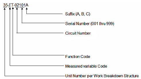
All components and functions of the loop shall carry the same tag number. The numbering shall be unique at loop level.
Each instrument shall have a tag number of the format:
abc yz
in which:
‘a’ is a three digit number used to identify the process unit.
‘b’ is a measured variable code: one capital letter code identifies the process condition, property measured or initiating variable. Where required, an additional modifier letter is added. (see the 1st letter identification table)
‘c’ is a function code: one or more capital letter codes identify the function of the instrument or loop. (see the 2st letter identification table) is a separation dash, used for clarity
‘y’ is a three digit serial number (i.e. from 001 through 999)
‘z’ is an optional suffix which may be used to make a loop component uniquely identifiable; only to be used if required.
P&ID Sample:

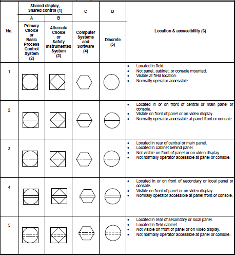
Instrumentation device and function symbols (As Per ISA 5.1 – 2009)
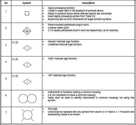
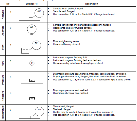
Instrumentation device or function symbols, miscellaneous
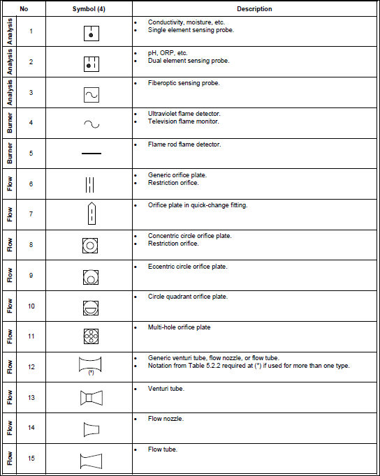
Measurement symbols: primary elements and transmitters

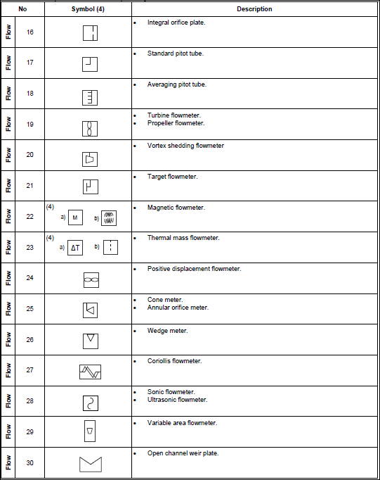
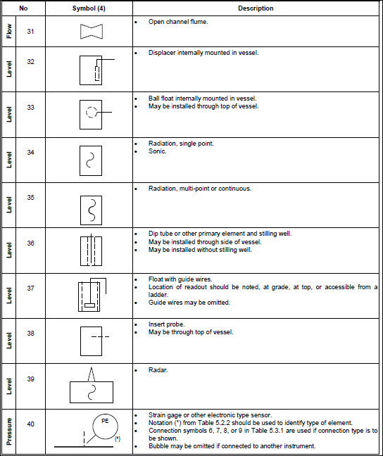
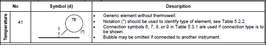
Measurement symbols: primary elements
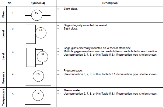
Measurement symbols: secondary instruments
Measurement symbols: auxiliary and accessory devices
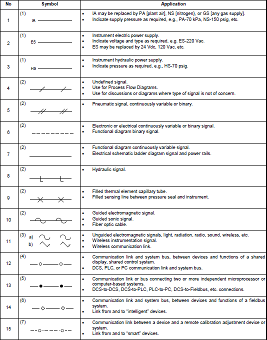
Line symbols: instrument to process and equipment connections

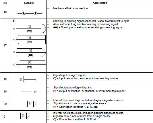
Line symbols: instrument-to-instrument connections
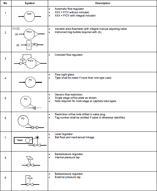
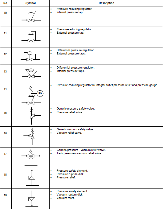
Final control element symbols
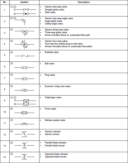
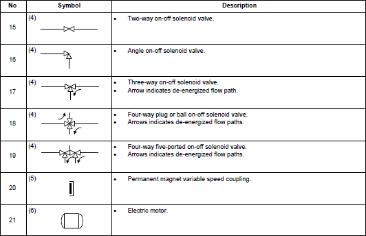
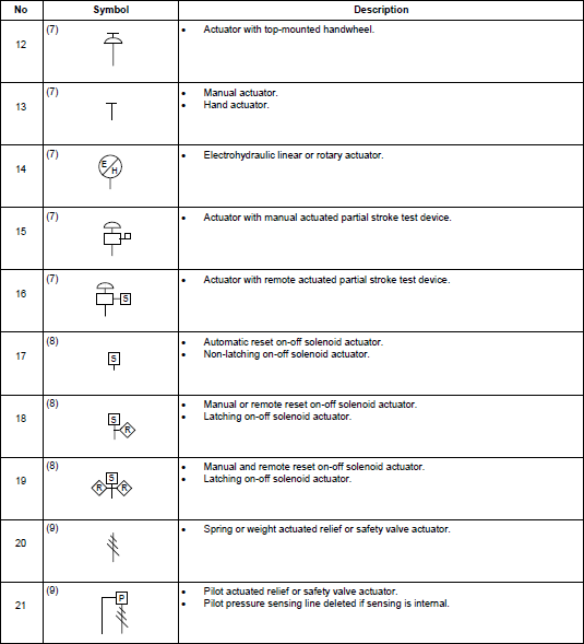
Final control element actuator symbols

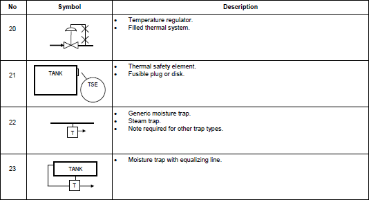
Self-actuated final control element symbol
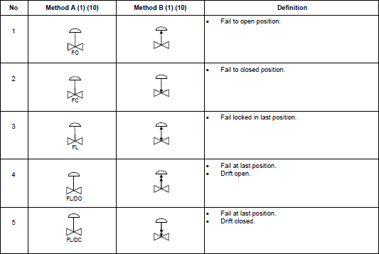
Control valve failure and de-energized position indications
Standard
ANSI/ISA-5.1-2009
Author - Ibnu Munzir