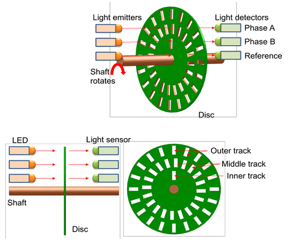
Optical encoders provide digital output as a result of linear / angular displacement. These are widely used in the Servo motors to measure the rotation of shafts.
The Figure shows the construction of an optical encoder. It comprises of a disc with three concentric tracks of equally spaced holes. Three light sensors are employed to detect the light passing thru the holes.
Optical Encoders
These sensors produce electric pulses which give the angular displacement of the mechanical element e.g. shaft on which the Optical encoder is mounted. The inner track has just one hole which is used locate the ‘home’ position of the disc. The holes on the middle track offset from the holes of the outer track by one-half of the width of the hole.
This arrangement provides the direction of rotation to be determined. When the disc rotates in clockwise direction, the pulses in the outer track lead those in the inner; in counter clockwise direction they lag behind.
The resolution can be determined by the number of holes on disc. With 100 holes in one revolution, the resolution would be,
360⁰/100 = 3.6⁰.
