The DeltaV DCS system consists of devices at the control and supervisory level.
As illustrated in Figure 1, the DeltaV DCS system in this research consists of workstation, two hubs, two system power supplies and two controllers for redundancy, and I/O cards.
DeltaV DCS system
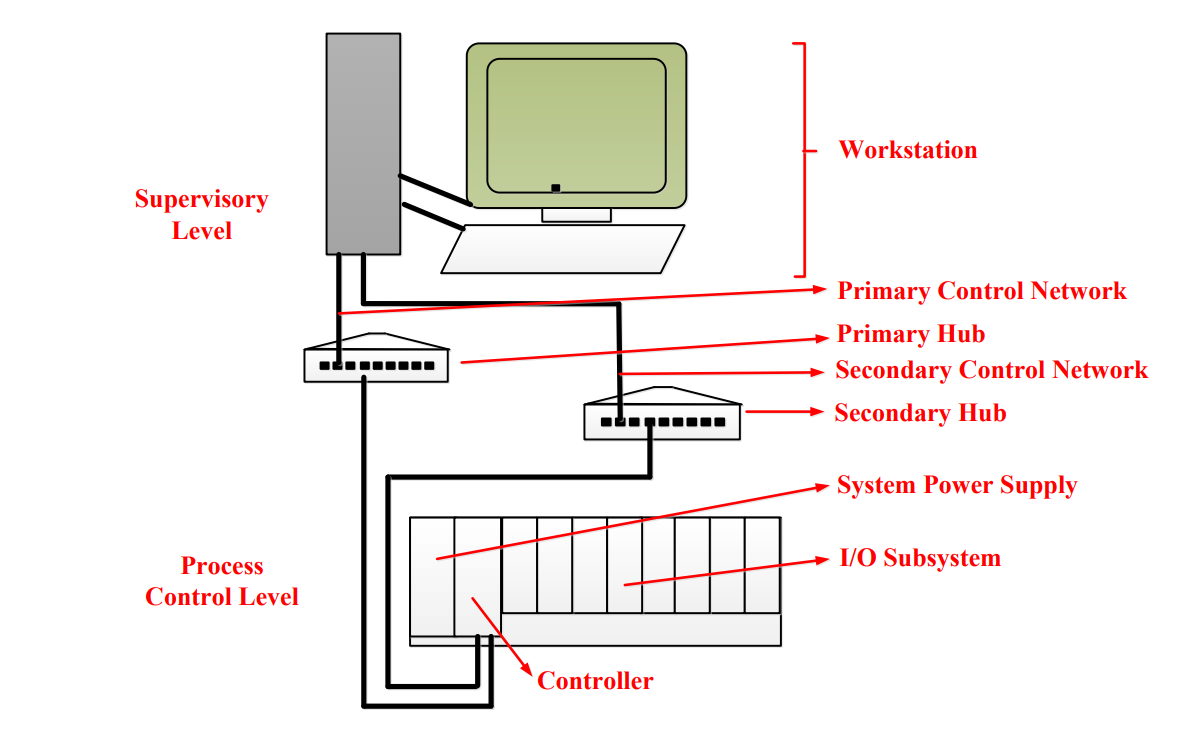
Figure 1: DeltaV system overview diagram
While the other components are standard design, I/O cards are different from project to project.
The workstation has all the software to configure the control strategies for the field device and HMI to monitor and operate process variables. The
The communication between PLC and computer is Ethernet with redundancy through two hubs. At the control level, two power sources supply DC power to controllers. I/O modules function as the interface between field devices and CPU.
Typically, there are four kinds of I/O cards: AI (analog input), AO (analog output), DI (digital input), and DO (digital output). I/O modules obtain data from field process and convert to discrete signal.
Output cards send the signal from the process unit to drive field devices. One important function of an I/O card is to isolate high level real world signals from low level signals in the I/O bus with optical isolators to protect the I/O card.
A/D converters in analog input cards convert analog signal to discrete signal for the/a process unit. D/A converters in input cards convert discrete signal to analog signal to drive field devices.
DeltaV cabinet configuration
All devices mounted inside the DeltaV cabinet are shown in Figure 3.2. They mainly include system power supplies (P1 and P2) which provide 12VDC power for controllers and other cards mounted on carriers, carriers which hold all the modules, controllers (C1 and C2), I/O cards (AI, AO, DI, and DO), switches, terminals, relays (R_DO1_1~8) and power supply (PWR1 and PWR2) for all devices in the cabinet. They are the devices at the control level.
Two power supplies, PWR1 and PWR2, convert 120VAC line power to 24VDC and provide 24VDC power to the entire DeltaV system in the cabinet. A circuit breaker (CB) is mounted before two power supplies to protect the system.
As indicated in the Figure 2, power supply number one (PWR1) supplies 24 VDC power to the system power supply P1 which converts 24VDC to 12VDC and carrier 3.
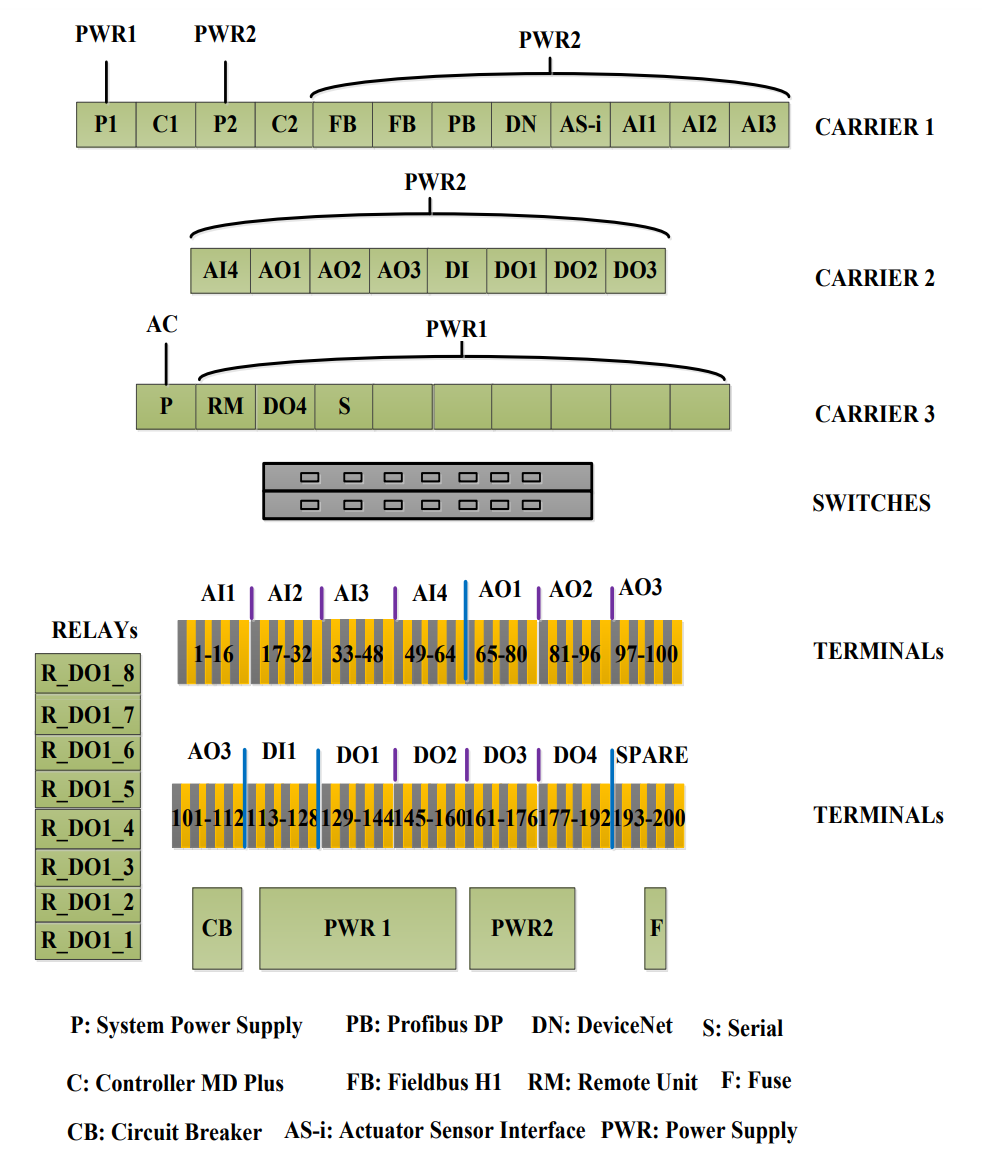
Figure 2 Device schematic diagram in DeltaV cabinet
Power supply number two (PWR2) supplies 24 VDC power to the system power supply P2 which converts 24VDC to 12VDC, other carriers, and DO intermediate circuit power through fuse F. Carriers provide power to all the cards mounted on the carriers.
The two switches have separated AC power supply. R_DO1_1~8 are relays used for connecting AC powered field devices to DeltaV DO cards which can only connect DC powered field devices.
Author: Ximing Liu